RMS Math
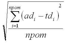
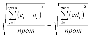
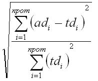
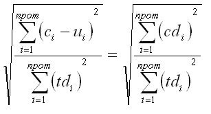
During the ANSYS Verification Analysis, the user has the option to calculate the RMS difference of the final mirror surface. The RMS calculations are always a comparison of two mirror surfaces. The RMS difference calculation varies between the "Reproduce Thermal Aberration" case and the "Correct Thermal Aberration" case. Furthermore, the Normalized RMS difference calculations have been normalized by the RMS of the thermally deformed surface.
| Reproduce Thermal Aberration | Correct Thermal Aberration | |
| Input | reverse actuator extensions | forward actuator extensions + thermal profile |
| Absolute RMS |
|
|
| Normalized RMS |
|
|
| where | ad are node deflections on the actuator deformed surface and td are node deflections on the thermally deformed surface. | c are the node locations on the corrected surface, u are the node locations on the undeformed surface, cd are the node deflections on the corrected surface, and td are the node deflections on the thermally deformed surface |
Notes:
deflection means change in position; UZ
location means absolute position; Z
npom is the number of sample points (nodes) on mirror surface