I’m converting an older road bike to e-assist. I want to keep the aesthetic of the older bike intact. This means keeping the Campagnolo Record 10 speed groupset currently on the bike. One thing to consider is how I’m going to control the motor. I want to keep the feel of a road bike, so I don’t want a thumb throttle. I also don’t want a cadence sensor governing power to the motor. So my only option is to install a torque-sensing bottom bracket. All of the torque-sensing bottom brackets on the market are made to JIS square taper standards. Campagnolo uses the ISO standard. Here’s what I learned about the interchangeability of these standards.
Primer
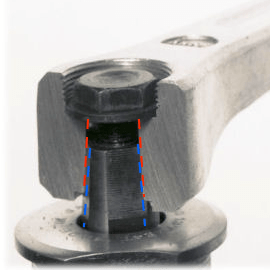
There are many ways to different solutions to mating bottom bracket spindles to cranks. A common way to mate these components is with a square taper. Sheldon Brown has a great cut-away image. I’ve annotated the spindle taper in blue and crank taper in red. As the crank bolt is tighened, the crank is “squeezed” onto the shaft. The hole “gets smaller” and the shaft “gets bigger” until there is a tight fit.
Two separate standards define the geometry of this interface: J.I.S (Japan) and ISO (international). It is up to the discretion of component manufacturers to decide which standard to follow. The problem comes when trying to mix and match compnents what adhere to different standards, as is my current dilemma.
What does the definitive source say?
The definitive source for all things bikes on the internet is surely Sheldon Brown. He has since passed away, but his website and its detailed knowledge are still relevant. His site dedicates an entire page to explain these standards with a section dedicated to their compatibility. He highlights that there are potential conflicts mixing and matching from these standards. This can lead to damage to the parts or even a crash if something fails catastrophically. Sheldon Brown also provides other examples of the crank not pressing fully into the spindle, resulting in a loose fit, again possibly causing deformation to the parts or an accident. He says
If you install an ISO crank on a J.I.S. spindle, it will sit about 4.5 mm farther out than it would on an ISO spindle of the same length.
I really wanted to dig into this 4.5 mm number. Sheldon Brown doesn’t provide any references to where this number comes from. More internet searching inevitably circles me back to Sheldon Brown’s website. Only after an hour of digging did it occur to me that because these are standards, I can read the standards themselves and compare them directly. So that’s what I did.
Let’s go to the standards
The first question I need to answer is which standard defines these dimensions. ISO has thousands of standards. Bike parts are a miniscule portion of their catalog. J.I.S. as a standard body was entirely new to me. A quick internet search laned me on a single result from 2007 on bike forums, where the poster hinted that two standard numbers. ISO 6695:1991 and JIS D 9415:2001. The discussion on that thread continues with more or less my same problem “show me the actual dimensions”.
As a side note, one of the posters links to a 2005 usenet discussion involving Sheldon Brown, Jobst Brand and others. It’s a fun rabbit hole and a helpful reminder that bike people have been arguing on the internet since the beginning of time.
Armed with these standard numbers, I went out and actually bought the standards, directly from the standard agencies themselves.
First up was I.S.O. Their website is easy enough to navigate. They are even kind enough to let me know that ISO 6695:1991 is out of date and has been superseded by 6695:2015. So I bought the newer 2015 standard. This document cost about 40 Swiss Francs (or about 45 USD). As you’d expect from anything coming out of Switzerland, this document is precise, straight to the point, but also chocked full of information. I can’t share the full document since it is technically copyrighted.
The first thing to note is the document is the responsibility of a specific committee ISO/TC 149, Cycles. I assumed that all of the members of this committee would be representatives from various bike component manufacturers. Instead the members are other national standard bodies from various countries (e.g. ANSI from USA). I can only guess that the bike component companies interact directly with their national standard bodies, who then work up to the ISO committee. I also expected to see more bike component standards corresponding to an ISO standard, but it seems this committee is quite limited. There is a list of which standards this committee manages.
One interesting side note is that the standard for “Cycles — Stem wedge angle” was updated in 2022. How did that ancient standard need updating in 2022?. I also love that there are some standards that haven’t needed updating since the 1980’s.
But back to the square taper standard itself. The document includes charts, and diagrams and even an update on how the 2015 version has been improved over the 1995. One specific callout is “in Table 1, dimensions and tolerances revised and specified;”. Sadly I don’t have any plan to buy the older 1995 version to see exactly what those changes are, even though it might give better insight into the 2005 and 2007 forum posts.
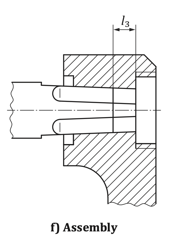
The critical parts of the standard are contained in Figures a, e, and f and Table 1. I have copied them here.

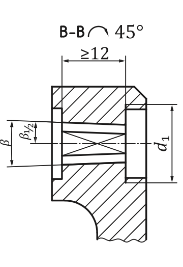
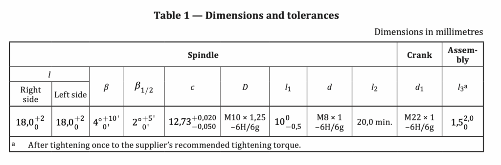
The critical dimensions are:
- a taper of 4 degrees, Beta
- a thickness of 12.73 mm, with tolerances extending that to between 12.68 and 12.75 mm, as measured 1.5 mm from the end of the shaft, c
- a length of taper of 18 mm, with tolerance extending that to 20 mm, l
- a length of crank taper of 12 > mm (listed as Od in Fig e, not Table 1)
- an assembly depth of 1.5 mm, l3
You’ll have to take my word for it that the other dimension in the table are not relevant to this discussion (they dictate things like thread depth of the crank bolt).
Another important detail is what is not covered by this standard. Everything “to the left” of the taper in this diagram is not defined in this standard, specifically how the square taper transitions into the round shaft.
We can now do the same sleuthing on the J.I.S. standard and compare the two.
Weirdly enough, J.I.S. standards are available to me in the US through ANSI’s website. I began by purchasing JIS D 9415:2001 for 39 USD. As with most things from Japan, it is incredibly detailed and goes deep into defining standards for cranks and spindles. The document contains 18 pages of standards for things like fatigue testing cranks and defining standards for the depth of chrome plating on certain parts. But it didn’t contain any dimensional information about square tapers. I went back to internet searching and found that this document is superseded by JIS D 9415:2019, something I failed to see on ANSI’s site when I bought the 2001 version. I ponied up another 39 USD to purchase JIS D 9415:2019.
Sadly this also didn’t contain any information on square taper dimensions, but it did call out that further information could be found in diagram JC 1.6 of JIS D 9301.
Back to the ANSI page to purchase JIS D 9301:2010, ensuring this was the newest standard available on their site. This document cost a mind boggling 139 USD, but I was already 120 USD into my search without an answer. I could either double that and get an answer, or call it quits. So I bought it. This document is monumental and covers basically every dimension of bike parts (aside from those governed by specific manufactures’ proprietary “standards”). In 93 pages, the document includes the aforementioned dimensional standards but also fatigue test standards for everything from complete frames and wheels, to cranks, seatposts, pedals. It includes diagrams for test rigs to measure saddle cyclic load testing. It includes a description on “low temperature test of synthetic resin saddle”. There is a section on what text must be included in the manual that accompanies new bikes. This document is insane. I can’t imagine starting a bike component company in Japan!. However, back to my quest, reading through the entire document reveals that there is no JC Annex. Another dead end.
Another internet search revealed that there is an updated 2019 revision of this standard. Unlike my previous blunder of not reading ANSI’s site carefully, for this document, ANSI doesn’t even have the 2019 revision listed on their site.
I then scoured the internet for a copy of JIS D 9301:2019 to purchase, but none was found. I did however find a bootleg version of this document in Japanese. So by relying on a random website to host a PDF, that Google Translate translated into english, I finally have an answer.
Note that all of this english is from Google Translate, so it will show up in any search results. The re-insertion of English into the tables makes them somewhat unreadable. But the critical information is there: Annex JC (Regulatory) Interchangeable Dimensions of Bicycle Parts. The first table within this section provides a first clue to the differences, explicitly called out here, by referencing the JIS and ISO standards by name:
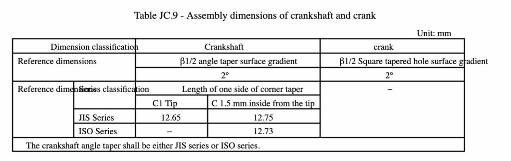
“C 1.5 mm inside from the tip” as 12.75 mm (JIS) versus 12.73 (ISO).
However further down the page, the document references the ISO standard in its entirety, duplicating the diagrams and tables and only referencing ISO dimensions
It takes a full search of the document to find any additional information about where this 12.75 value comes from. I eventually find a diagram and table in the previous section JC.1.5 Assembly dimensions of hanger parts and frame body
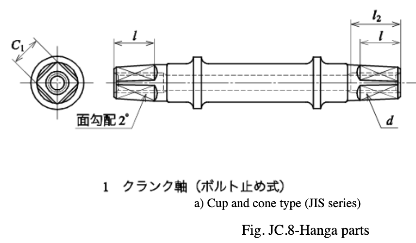

This provides dimensions as follows:
- a taper of 4 degrees, Beta
- a thickness of 12.75 mm, as measured 1.5 mm from the end of the shaft, C
- a length of taper of “more than 15 mm” (for cranks that fasten with a bolt, not a nut), l
Comparison
With the relevant dimensions, these standards can be compared. The taper dimension for both standards is in fact 2 degrees, from the axis of rotation. It is safe to say the entire internet was in agreement with this, to the point of it being common knowledge.
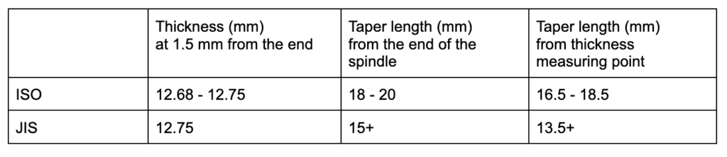
The only relevant differences between these two standards are the “thickness at 1.5 mm from the end” and the taper length. Let’s put these values into a simple table:
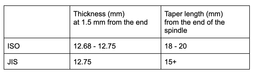
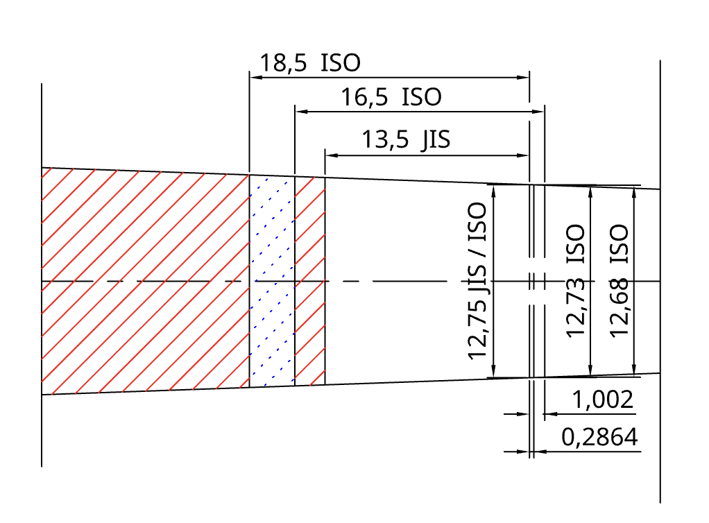
Now let’s take these dimensions and create some additional drawings to visualize these standards side-by-side. Start with a 2 degree taper spindle which extends in both directions an arbitrary amount and add three vertical lines for the standard max and min values. This let’s us measure the max and min horizontal distances between these standards.
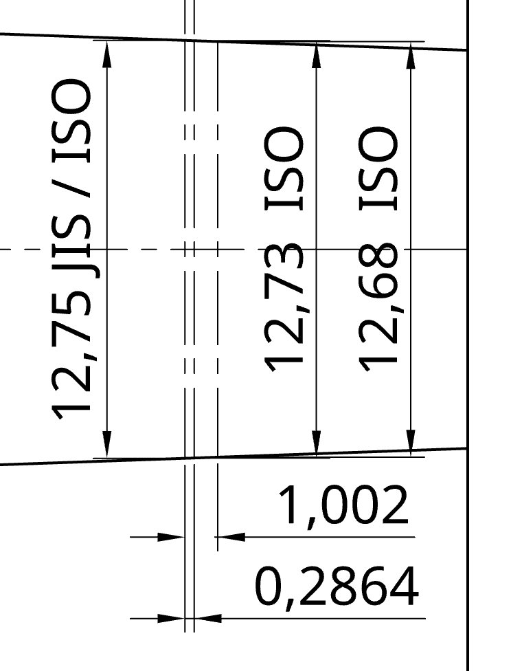
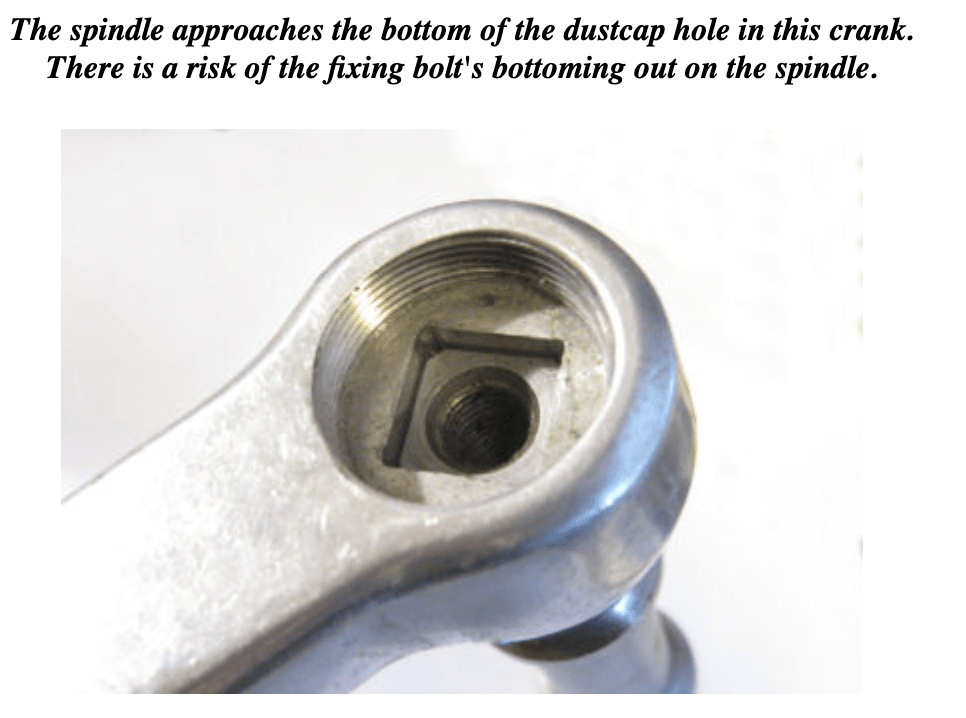
The tolerances on the ISO standard put the thickness value at between 12.68 and 12.75 mm, which includes the JIS standard’s exact dimension of 12.75 mm. These thickness differences, on a 2 degree taper, result in a maximum axial difference of 1 mm. That is quite significant given the “assembly distance” (labeled l3 in the diagrams above) is only 1.5 mm. To “lose” 66% of that gap by putting a 12.75 crank on a 12.86 spindle is significant. But it’s important to see this is not strictly an JIS / ISO interchangeability issue. Because of the tolerance range of the ISO standard, an issue could also arise when mating an ISO crank at the large end of the tolerance range with an ISO spindle at the low end of the tolerance range. Sheldon Brown is correct that the fixing bolt is in danger of bottoming out on the spindle, but this is a potential issue with all crank/spindle combinations.
The significant differences between the two standards come when comparing the length of the taper. Let’s extend our drawing to plot the locations of the length of the taper. Remember that these lengths are from the end of the spindle, not the thickness measuring point (1.5 mm inboard from the end). So to plot these lengths relative to the thickness measuring point, subtract 1.5 mm. Let’s add a column to the table.
The JIS range is straightforward, since the standard is exact about the 12.75 thickness and lists a 13.5 mm or greater taper length. The ” face of the crank” will be anywhere within the red stripe or blue dot regions. The ISO standard is a bit more complex since it includes ranges for both thickness and taper length. Paring the smallest taper length with the smallest thickness, results in the “most outboard position”, which is the right edge of the blue dot region. Pairing the largest taper length with the largest thickness, results in the “most inboard position”, which is the left edge of the blue region.
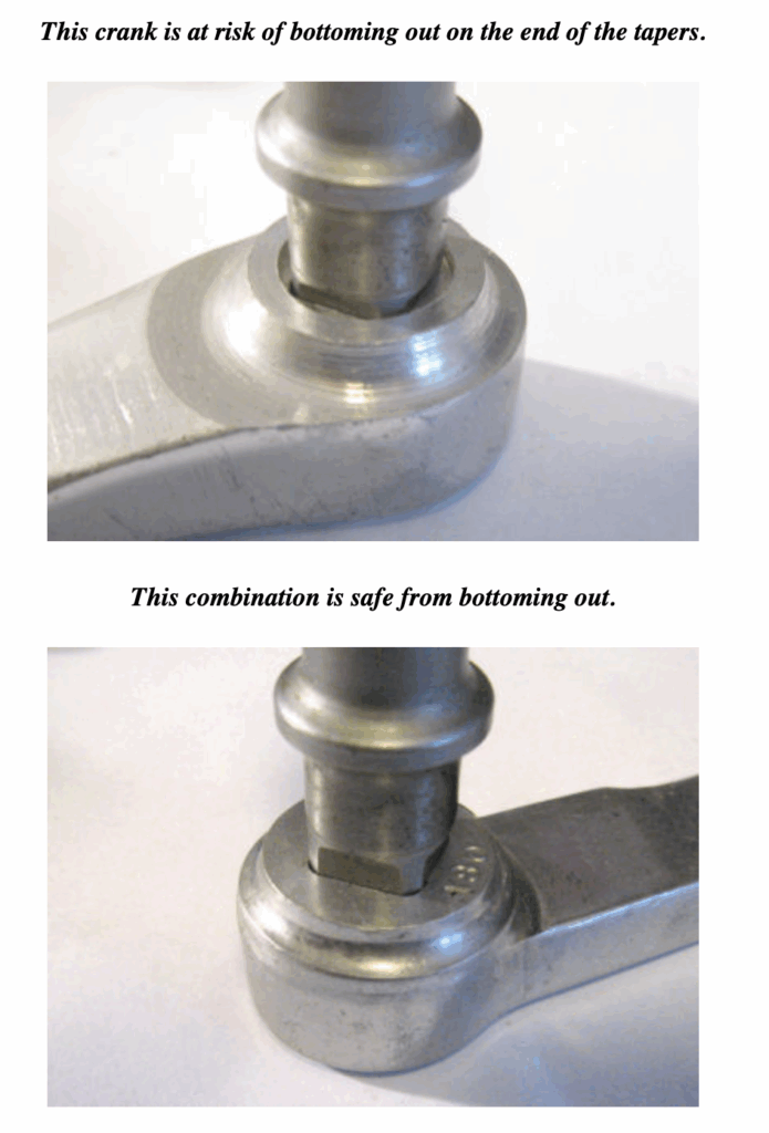
Here we can finally visualize the potential issue with mixing and matching standards. Let’s see some examples in action using two different JIS spindles, paired with one possible ISO crank. In the first case, creating a JIS spindle with the minimum 15 mm taper length, the crank bottoms out on the spindle flange before engaging the tapered portions. This is the unsafe and unstable situation to be avoided.
In the second case, let’s increase the JIS spindle’s taper length to 18 mm, still within the range allowable by the spec. Positioning the interior and exterior tapers coincidently results in a gap between the spindle flange and the crank edge. This is the safe desired position.
These two examples demonstrate the same problem Sheldon Brown highlights when he shows that a crank can be in jeopardy of bottoming out on the spindle.
So what?
It’s important to realize the question is not as simple as “Does JIS fit on ISO?”. It is entirely an issue of “Does this specific crank fit on this specific spindle?”. This is the same conclusion that Sheldon Brown came to twenty years ago. Buried in the forum post, Sheldon Brown says
“.. some of us are of a more experimentalist turn of mind. For this sort of approach, trial and error is often the only way to go, since the “specs” do not exist or do not apply to the application.”
He’s partially right. The specs do exist, but they overlap enough, and include tolerances such that trial and error is the only way to see how well they fit together.
Chainline and Q factor
My concern is about mechanical safety, ensuring the crank and spindle press-fit together, preventing any mechanical failure or loosening of the joint. However if a repositioning of chainring or pedal inboard or outboard is a concern, Sheldon Browns suggests to expect a 4.5 mm change inboard or outboard from mismatching. My research and drawings do not show this to be true. Assuming no issues with the crank bottoming out on the spindle, a mismatch will only result in +/- 1 mm change in position of the pedal and chainring. I still have no clue where this 4.5 mm value is coming from.
Campagnolo and ISO Standard
In all my research I couldn’t find a single official source saying that Campagnolo conforms to the ISO standard for their cranks/bottom brackets. Given that Campagnolo is notorious for ensuring compatibility within their own product catalog and not concerned about compatibility with other component manufacturers, its possible they don’t conform to any public standard and instead have their own specifications. Their “internal” standard may be close to ISO but not exact. So my compatibilty question is technically “do Campagnolo cranks work with JIS bottom brackets?”
Phil Wood Gauge
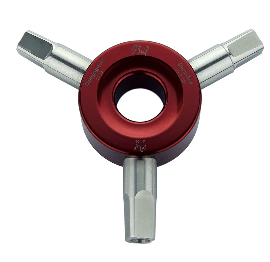
I am confused that Phil Wood makes this Square Taper Bottom Bracket Fitment Gauge for checking whether a crank will fit on an ISO or JIS bottom bracket. Given the variability I already discussed in these standards I’m not sure I would trust this as a go / no go tool. A pair of calipers with a depth gauge could easily measure the relevant dimensions on both the spindle and crank in question.
This was a deep dive into some very boring and tedious technical details. Thanks for making it all the way through.
Thank you, Jason!
Since I found a Stronlight/Solida spindle and a Gipiemme crankset in the parts bin and searched for information on its possible matching, I’ve been quite interested in spindle/cranks dimensions and compatibilty.
This is, by far, the most accurate and enlightening discussion on this subject I ever found.
Hi Jason and all,
Thanks a lot for this work. It is helpful!
I found a preview of the 1991 version of ISO 6695. The preview only shows the first four pages of the standard. But it happens to be enough to read what the sizes of the taper are supposed to be.
As it turns out, the issue is not the difference between ISO 6695:2015 and JIS D 9415:2019. These are practically identical. The issue is that the dimensions changed from ISO 6695:1991 to ISO 6695:2015.
Sheldon Brown would have had to deal with the 1991 version – and with bicycle cranks from the seventies and eighties, before the first version of ISO 6695 was published.
In ISO 6695:1991, the width of the taper on the axle is still measured at a depth of 1.5 mm from the end of the axle. But the width, here, is supposed to be 12.6 +0.02/-0.05 mm (as opposed to 12.73 + +0.020/-0.050 mm in ISO 6695:1991).
The same crank arm will sit 1.9 mm deeper on a nominal ISO 6695:1991 axle than on a nominal ISO 6695:2015 axle.
The same crank arm will sit 2.9 mm deeper on a minimum ISO 6695:1991 axle than on a maximum ISO 6695:2015 axle or a JIS D 9415:2019 axle.
I wonder if JIS axles are made with a tolerance of less than 0.01 mm? And if the taper may also have had a different size in older versions of JIS D 9415?
(Trying to add some html formatting to the same post, to make it more readable…)
Jensen,
Great find! Please share those images if you can.
Hi again,
Here:
https://standards.iteh.ai/catalog/standards/iso/e404a137-8c8c-414a-9a1d-17acc873a189/iso-6695-1991
There are links to previews in different languages.
Also. Is the definition of the taper hole in the crank arm a little sloppy in JIS D 9301:2019 ?
If I get it translated correctly, on page 52 the crank arm is simply defined by, that it has to fit on either a JIS spindle or an ISO spindle. And then on page 53, where JIS D 9301:2019 refers to what the dimensions in the ISO norm are, the l3 dimension of 1.5 +2.0/-0 mm in ISO 6695:2015 get misspelled as 5.1 +2.0/-0 mm in JIS D 9301:2019 – or perhaps that is only in the bootleg version?
(l3 is the dimension that says how deep the end of the spindle has to go into the tapered hole in the crank arm).
I wonder if this could have caused some odd-sized crank sets out there 🙂
In my opinion, the international and Japanese standards do not differ in terms of dimensions. The Japanese standard references ISO 6695, including the 1991 version in editions such as e.g. those from 2003 and 2008. And 6695 is about the dimensions only.
JIS is, of course, a member of ISO, and I wouldn’t be surprised if these dimensions were actually proposed by them.
And certain inconsistencies and unusual values, such as those found by Jensen, may stem from errors in the presentation of information rather than intentional differences.
Oh, I forgot to add.
I forgot to mention that I’m almost certain these differences might be due to the conversion of 1/2 inch to millimeters.
1/2” = 25.4 mm / 2 = 12.7 mm (exactly)
12.7 mm + 1.5 mm * tan(2 deg) ~= 12.7524 mm
@Jensen l3 dimension is the same in 9301:2019 1.5+2.0/-0mm. This is a problem with the “bootleg” version. The text isn’t original. It was probably OCR-ed.
In my previous message about inches-mm conversion unfortunately I made a mistake. 1/2” thickness must be in the middle of the range. So probably 0.75 mm from the end. Maybe 1/2” was defined at .030” distance (.060” / 2). But it doesn’t matter too much. My thesis is the standards were never really different and in the comparison showing the differences between the national standard and ISO, JIS wrote about 6695:1991/9415 in the 2000s:
JIS specifies requirements for all aspect of chainwheels and cranks besides safety and dimensions which are part of ISO.
Rabbit hole…
JIS D 9401 (“Bicycle frames”) is another standard that includes, among other things, the dimensioned drawings that are the subject of this blog entry.
And the dimension that interests us most is specified as 12.65 mm again.
Theoretically that’s enough as the taper angle 2 (or 4) deg is given, @1.5 mm: 12.65 mm + 1.5 mm * tan (2 deg) * 2 ~= 12.755 mm. The minimum length is 15 mm for the bolt version and 16 mm for the nut.