When I was an undergrad at Georgia Tech, I worked on a research project for a year. I worked part of the time while still in school and continued after I graduated. I didn’t really have a senior design project and most undergrads didn’t do actual “research”. So, I felt pretty lucky to be involved in a real research project, especially given the level of my involvement. I worked with Dr. Harvey Lipkin and his grad student Russell Marzette Jr. Russell and Dr. Lipkin had developed a new way to actuate (bend and position) really large telescope mirrors and it was my job to develop software to model and test this technique. I wrote some MATLAB and ANSYS code to automate all of my tests. What was really cool (and unknown to me prior) was that I could use ANSYS from the command line and write scripts which match a normal GUI work flow in the 3D environment. I could create structures, apply loads, mesh structures, and run simulations all from scripts. This allowed me to create a MATLAB GUI to set parameters (or sets of parameters), create and execute custom ANSYS scripts, and format ANSYS-generated image and text results. I could set a span of parameters and run an entire batch of ANSYS simulations back-to-back. These were special mirrors, about two meters across and designed to operate in the low gravity of space. As such they could be really really thin, only 0.1 millimeters thick. These mirrors were prone to change shape as the telescope itself heated up and cooled down from exposure to the sun. Any change in their shape or size would greatly distort the image the telescope was capturing.
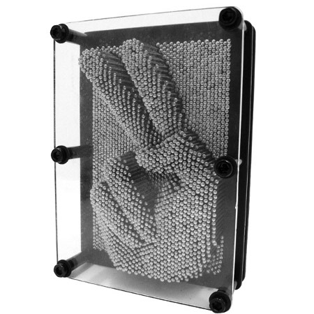
The current solution to support and control the shape of the mirrors was to create a rigid backing structure with many many linear actuators. Each actuator would push perpendicular to the mirror surface. You can image a grid of actuators like this Pin-Art toy pushing against a thin surface:
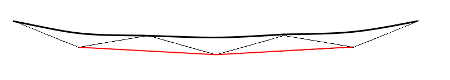
However, this new technique was of a more geometric configuration. Take, for example, a two-dimensional truss structure that supports a film. Two linear actuators (in red) are aligned in a single direction and each can lengthen or shorten. As they change length, they deform the shape of the mirror (bold black).
Now extend that to a 3D structure, with actuator arranged in two-directional grid.
The mirrors were hexagons not circles, because, in theory we could put many two-meter hexagons together to make a 50+ meter diameter mirror. We could vary the density of these actuators, but the configuration was always the same. We tested structures with 15, 43, 93, 159, and 1563 actuators.
The mirror would change shape as it was exposed to some temperature, either uniform temperature, or some temperature profile. The first thing I needed to do was understand how the mirror and the truss structure changed shape when heated. So I did some analysis and heated it up (first just the mirror) and then the entire structure. Some cool results came of this. Obviously the truss and the mirror were not deforming “together”. One was pulling the other.
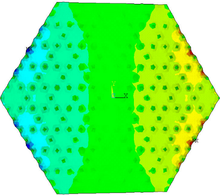
Thermal deformation of the mirror and the underlying truss.
So, now that I knew how the mirror was deforming, I needed to get to the real point of the research. Could this new geometry correct these deformations. And, if so, how few actuators would be needed. The basic theory is that if we can move the actuators from a “resting” position to produce the same shape as the thermal deformation then if the mirror is already deformed we can more the actuators in the opposite direction to correct the deformation and return the mirror to its normal shape. So I first confirmed that I could reporoduce the thermal “abberations” and then applied those actuator movements to the thermal abberation to “correct” the mirror back to normal.
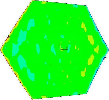
Error between un-deformed and corrected mirrors in the z (out of the page) direction. Green area is 0.1 micron error.
So this worked out pretty well. However, these linear actuators didn’t physically exist yet. There was another team designing them. So we needed to provide some feedback to our sponsors about what conditions the actuators might experience. Each simulation outputs maximum stress values and any torsion or bending moments experienced by the actuators. We also add the ability to change the coefficient of thermal expansion (CTE) of each element (mirror, truss, and actuator). Differences between truss and actuator CTE caused most of the deformation, as we learned.
We also knew that the actuators would have some error, but we didn’t know how much. One of my major contributions was realizing that we didn’t even know what kind of error. I figured that the actuators would eventually work in one of two ways. They would either be continuous and have some +/- error around the desired position. For example if the desired position was 0.456 mm, it could possibly be at any position 0.456 +/- 0.01 mm. Instead, the actuators could be discrete and have some absolute error but ratchet to discrete locations. For example, if the desired position was 0.456 mm, it could actually be at any of several discrete points (0.400, 0.450, 0.500 mm). So I was able to model both of these error types into the GUI.
In the end, as our project was growing quite large, I documented the entire code base and created a pretty slick little help document including some very boring how-to videos. Have a look and see if any of it makes sense. I also added a gallery of pretty pictures if thats more your thing. Lastly, I’ve included my presentation and Russell’s thesis, both interesting.