As part of my ME degree from Georgia Tech, I had to take a class called Experimental Engineering (ME 4055). It was a senior level class where students worked in teams to complete a project that mimicked the research cycle of a PhD student or professor. The team was required to design and conduct a set of experiments, evaluate the results, and then write a paper. For most students this was a rather bogus class. Students were limited to a small amount of hardware and research areas, and each semester’s reports looked all too similar to previous. I, however, had the very special chance of taking this class with Adam Reich during my semester abroad at Georgia Tech Lorraine (GTL), which meant working with Dr. William Singhose and his PhD student, Jason Lawrence. They were at GTL to teach several other classes (another one I was also in, ME 6401 Linear Control Theory) and to continue/promote their research with a highly portable, miniature gantry crane.
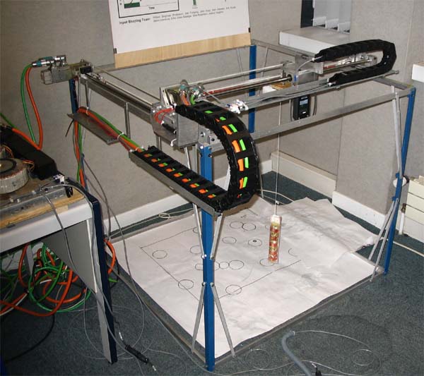
The mini gantry crane setup at GTL. Dr. Singhose and Jason Lawrence’s research focused on developing input shapers, which are open-loop control algorithms designed to minimize residual vibrations in the gantry’s payload. Input shapers have been developed to address many different conditions and desired results and Jason Lawrence had recently invented a new one. Adam and I decided that it would be our responsibility to actually test Jason’s new input shaper and benchmark it against existing shapers.
The easiest way to visualize an input shaper is a set of on and off commands to the drive motors. The timing and magnitude of these on and off pulses define the shaper. Furthermore, a shaper includes both the set of commands which start the motor and the set of commands which bring the motors to a stop. The input shaper is implemented by convolving the shaper with the desired command to create the shaped command.
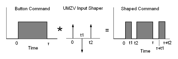
Figure 1. Convolving equation, using Unity-Magnitude Zero Vibration Shaper as an example.
Most drive motors which control the bridge and trolley do not perform in a linear fashion; they do not have infinite acceleration. In other words, the motors take some time, even if its a fraction of a second, to speed up and slow down. These non-linearities increase even further if the ramp up (acceleration delay) time is different than the ramp down (braking delay) time. Our goal was to test three input shapers and determine their effectiveness as we varied the ramp up and ramp down times. We contrasted their performance against a fourth case: no input shaping at all.
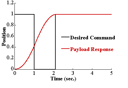
Figure 2. Command and payload response when the drive motor has infinite acceleration.
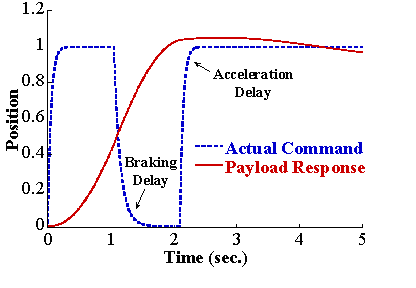
Figure 3. Command and payload response when the drive motor has exponential velocity.
The best way to visualize the residual vibration is on a 3D surface plot. High elevations correspond to large residual vibrations and low elevations correspond to little or no residual vibration. The two horizontal axes are the input ramp up and ramp down times. A perfect input shaper would produce a flat surface of zero elevation.
The first case we examined was the case of no input shaping. In Figure 4, the large peak in the “back” forms as rise and fall times become shorter.
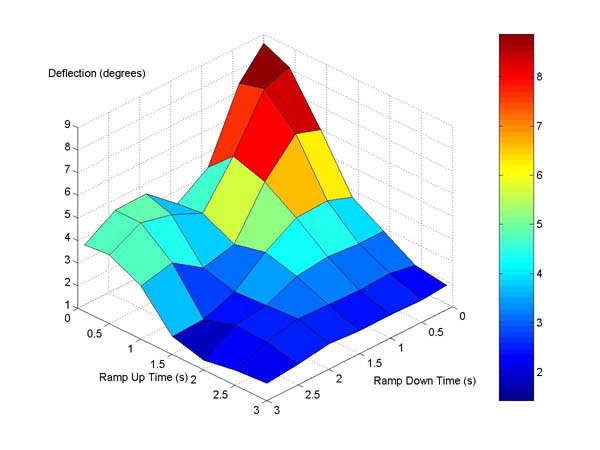
Figure 4. Surface Plot of Residual Vibration for No Shaping.
The next shaper we tested was the most basic input shaper called a Zero Vibration (ZV) shaper. In Figure 5, the large peak is gone and a rather uniform valley appears along the diagonal. This demonstrates that the ZV shaper is effective when the rise and fall times are the same. Its also evident that the shaper increases residual vibration in some non-linear cases.
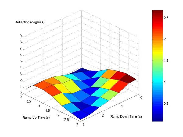
Figure 5. Surface Plot of Residual Vibration for ZV Shaping.
The second shaper we tested was a shaper which is optimized for speed, called a unit-magnitude zero vibration shaper (UMZV). This shaper performed better in all cases except near-infinite motor acceleration and, unlike the ZV shaper, was able to reduce vibrations in the non-linear regions.
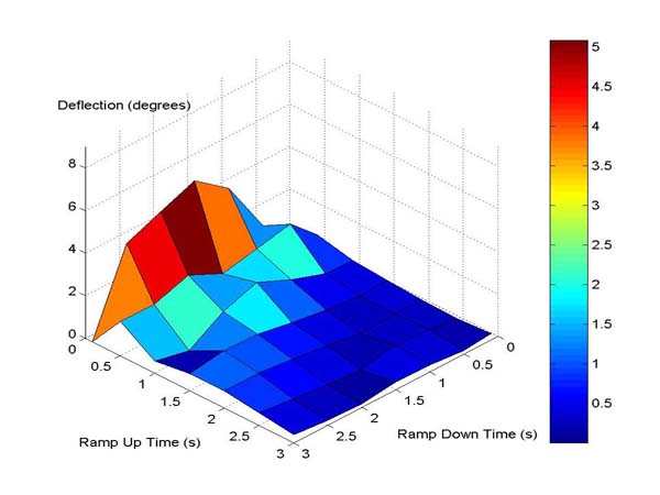
Figure 6. Surface Plot of Residual Vibration for UMZV Shaping.
The final shaper we tested was Jason Lawrence’s modified UMZV shaper which was designed specifically to deal with these non-linearities. Because of an early decision in our experimental procedure, we commanded the drive motor with a linear velocity (i.e. constant acceleration). However, the modified UMZV shaper was designed to deal with exponential velocities. In our report we document our attempt to compensate for this discrepancy. Ultimately, our incorrect attempt resulted in rather poor and overall sporadic results of this modified UMZV shaper.
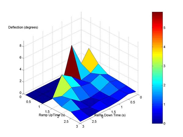
Figure 7. Surface Plot of Residual Vibration for Modified UMZV Shaping.
After Adam and I submitted our final report, I had the very special privilege of presenting our work to quite a few German representatives from Siemens, our sponsor. This was the first time I had to present directly to industry personnel, not professors or classmates.
In writing and assembling this entry, I had to go back and completely rebuild our report. At the time of presentation (at GTL) there was only one printer in the whole school, and it happened to be a black and white printer. Adam and I were so meticulous about our data storage and figure organization that I was easily able to pick up exactly where we left off. The paper I present below is a reworked version of our original with all color figures.
It seems that our research was grounds for Dr. Singhose and Jason Lawrence to continue studying the effects of these non-symmetric type nonlinearities. Resently, a journal artical was published by the Georgia Tech Input Shaping Lab which, I hope, our work helped guide in the right direction. I took a minute and grabbed a copy of their paper from the GT Library and include it below with our full report.
Download: Atwood, J., Reich, A., “Robustness of Input Shaping to Non-linear Crane Dynamics”, 2004
| Adobe Acrobat (.pdf) |
Bradley, T. H., Danielson, J., Lawrence, J., and Singhose, W. “Command Shaping Under Non-Symmetrical Acceleration and Braking Dynamics.” ASME Journal of Vibration and Acoustics, 2007, Vol. 130, 04503 pp. 1-5.
| Adobe Acrobat (.pdf) |
Siemens Presentation
| Microsoft Office Powerpoint (.ppt) |