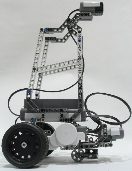
So in the course of finishing what would have been part 3 of this project, the post processing, I decided that some design changes needed to be made to the robot. I made two hardware changes: larger drive wheels and the addition of a compass sensor.
I also found that when I put the robot through some tests in a maze, the robot was not always turning smoothly. Some times the bot would get stuck or the wheels would start slipping. Because the robot was determining its change in heading based on data from the motor encoders, any deviation from perfect, nonslipping rotation would cause errors in the robot’s perceived heading change. This error would propagate quite quickly through consecutive iterations, causing gross inaccuracies in localizing the robot, and subsequently mapping the environment.
I decided to add HiTechnic’s compass sensor to read out the absolute heading of the robot. It was quite easy to update the code and luckily NXC/BricxxCC can handle this sensor.
The sensor is not well documented, especially when using NXC/BricxCC. After some googling I found that the key to using the compass sensor is setting the sensor type and reading data from it. To set the sensor use the Lowspeed option:
To take readings from the sensor use the NXC built-in HTCompass command:
After using the sensor and realizing the built-in compatibility for this sensor, I was surprised at how easy it was to use despite how little documentation existed on the web. Neither HiTechnic nor NXC have any documentation about implementation on their sites.
For anyone new to the sensor, I wrote a quick script that allows users to test their HT compass sensor in the NXC environment”
[iframe src=”https://jasonatwood.io/wp-content/uploads/2009/10/compass_test.html” frameborder=0 width=640 height=380]
The compass sensor outputs a value between 0 and 359 to represent 360 degrees of rotation. The important aspect for me is that it that there is no error propagation. The sensor has a resolution of 1 degree and certainly has some error. (I may run some tests on this sensor in the future). However, whatever the error, it will be constant and not add up with each turn.
Additionally, the compass sensor can experience magnetic interference from the motors and the brick so I positioned it, as HiTechnic recommends, four inches from the brick and six inches from the motors. The robot certainly has a more menacing look now.
The NXC code is updated to reflect the changes in heading calculation.
[iframe src=”https://jasonatwood.io/wp-content/uploads/2009/10/slam5.html” frameborder=0 width=640 height=1650]
thanks for good information