The challenge Design and build a machine that fires Nerf foam balls and hits static and moving targets with great accuracy and speed.
The team Four engineers joined forces to accept the challenge.
<
p align=”center”>
The machine
<
p align=”center”>
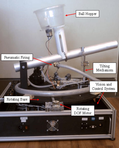
Tasked with designing an end system to identify and strike targets with a given rate and accuracy, the team divided the complete system into four subsystems; firing, loading, vision/tracking, and aiming. By evaluating how elements of each of these subsystems impacted the overall system performance goals, the team was able to solidify design choices.
We realized early on that firing accuracy was a key component of a successful design. Thus, we emphasized this subsystem early on. We compared two types of firing mechanisms: flywheel(s), similar to a pitching machine, and pneumatics. In the end, we decided to use pneumatic firing due to its firing speed and accuracy. Using compressed air to shoot cause the balls to attain such a high velocity that they follow a straight-line trajectory. This allowed us to ignore any ballistic movement of the ball and fire directly at a target guaranteeing a hit.
The aiming subsystem was not contingent on the firing subsystem and was thus independently realizable. However, due to the fact that we chose to use a pneumatic firing system, we knew we needed to have two aiming degrees of freedom for our device. Thus, we have one degree of freedom that allows for horizontal panning in order to reach the left and right extremes of the target testbed. We also have a second degree of freedom which allows for vertical tilting of the barrel. This is necessary to hit the targets at three different heights.
The vision system relies upon a CMUCam image processing camera for identifying targets, connected to an Arduino Uno microcontroller to provide the aiming subsystem coordinates to fire upon. We chose to use the CMUCam over a webcam or a WiiMote because its performance of the specific task of finding the centroid of an object based on a defined set of red/green/blue values. This allowed the machine to easily finding circular red, green, and blue targets against a black background.
The loading subsystem was the last subsystem we evaluated. We wanted to use as little actuation as possible and base our design off passive funneling of the balls into the firing barrel. Our goal was to reduce the number of sensors and components, thus creating fewer potential failures. However, due to the size and material of the balls, it was necessary, to include some agitation in order to avoid jamming of the balls.
Vision Subsystem
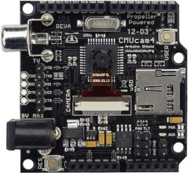
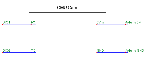
The vision subsystem has one main component: the CMUCam. Our machine uses the fourth generation of this camera. The camera is powered from a 5V supply via the Arduino Uno. Through a built-in software serial library the Arduino Uno is able to use two digital general purpose in/out (GPIO) pins as the transmit (TX) and receive (RX) pins to send commands to and receive data from the CMUCam. Once commands are sent from the Arduino to the CMUCam, the Arduino parses the returning messages sent from the CMUCam. With this two-way communication between the CMUCam and the Arduino, the vision subsystem is able to track the location of static and dynamic targets. The CMUCam has an API that allows for finding the horizontal and vertical location of the centroid of tracked pixels. Tracked pixels are those pixels that are within red, green, and blue range and are within the set bounding box of the field of vision of the CMUCam.
<
p align=”center”>
<
p align=”center”>
Aiming Subsystem
Using the vision system to locate and track the static and dynamic targets, the mechanical device has to be capable of aiming the barrel at the entire range of the target test bed. Since the three targets are located at different heights and are capable of moving in the horizontal direction, we designed a system with two degrees of freedom for mechanical aiming.
<
p align=”center”>
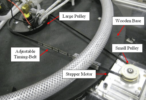
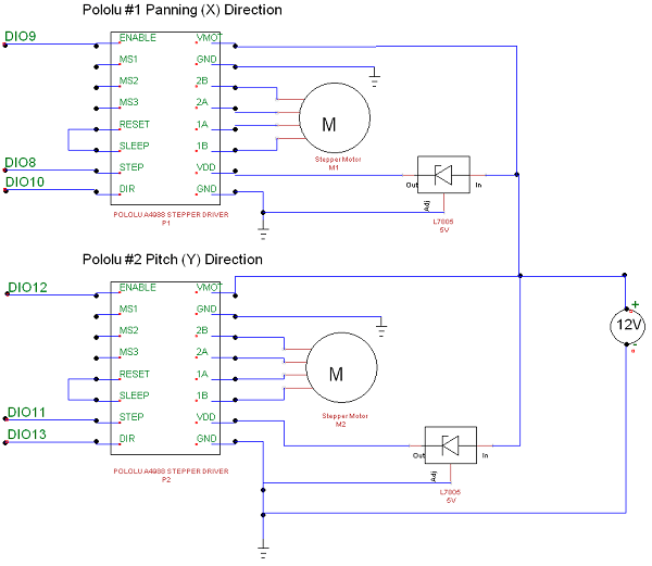
Panning of the robot is accomplished using a stepper motor-driven timing belt system. A circular, wooden base-plate is mounted to a ball-bearing turntable. Bolted to the center of the base-plate is a timing-belt gear with 120 teeth. Attached to the shaft of a stepper motor is second timing-belt gear with 30 teeth. An adjustable-length timing-belt couples the two gears, providing a total gear ratio of 4, which increases the angular resolution with which we can rotate the base plate. The resolution of the stepper motor is 1.8deg/step. Thus, driving the motor one step leads to a base-plate rotation of .45 degrees. This timing belt mechanism allows the system to rotate, such that the barrel can aim at the left- and right-most extremes of the target testbed.
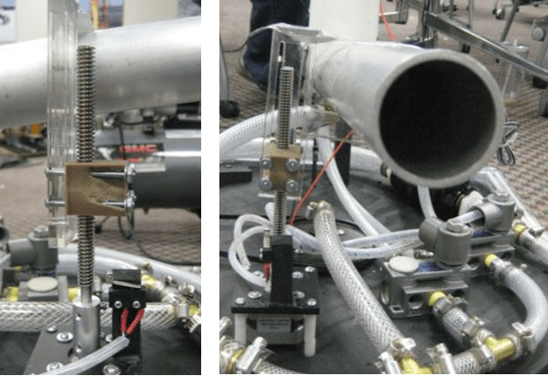
Tilting of the barrel is achieved through a motor-driven lead-screw mechanism. A lead-screw is rigidly coupled to the shaft of a small stepper motor. This stepper motor is mounted to the rotating based of the system. The lead-screw nut is bolted to a u-shaped bracket made from acrylic. The front of the barrel uses gravity to rest on the bracket. Driving the motor rotates the lead screw, thereby moving the lead-screw nut, and consequently the bracket holding the front of the barrel up and down. The rear of the barrel is held up via two wooden, vertical supports. A shaft attaches to these supports and goes through the barrel. Thus the vertical position of the rear of the barrel is held fixed, but it is allowed to rotate about the axis of shaft. As the motor is driven left and right the barrel tilts up and down, ensuring that the system can hit targets at the three different vertical heights.
<
p align=”center”>
<
p align=”center”>
Firing Subsystem
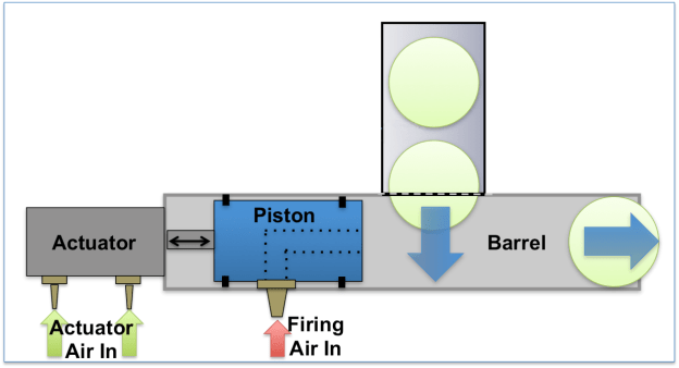
The firing subsystem has two main components: a solenoid actuated piston and a firing solenoid. As shown in the schematic below, a pneumatic linear actuator retracts the piston for loading then extends to force the ball in the barrel. With the piston still forward, the firing air is routed through the piston to project the ball.
<
p align=”center”>
While the simplified schematic just shows the air inlets for the two components, the actual implementation is quite involved. Figure 9 shows the actual firing subsystem complete with air lines and solenoids.
<
p align=”center”>
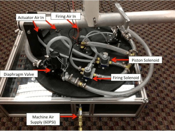
As shown, the compressed air inlet is routed through the frame and up through the rotating base via a rotary union. For piston actuation, air is routed to the piston solenoid to pressurize the front or back of the linear actuator, depending on the solenoid position. Firing is slightly more complicated due to the large volume flow of air required. Here, the firing solenoid only acts to close or open a large diagram valve. The air used to fire the ball actually passes though the diaphragm valve, not the firing solenoid.
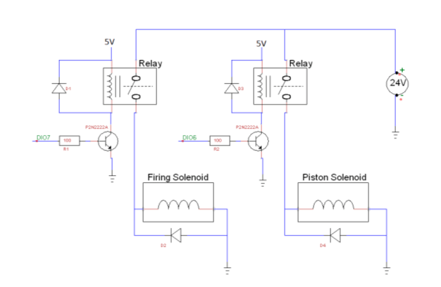
In order to actuate the solenoids, which operate on 24VDC, a relay and transistor were used. The relay was used in order to switch the 24V signal with a lower 5V signal. Although the Arduino digital outputs are 5V, the current was not sufficient to switch the relay. A transistor was used at the microcontroller output to control an external 5V signal to switch the relay, which then switched the solenoids. The circuit diagram for the firing subsystem is shown in Figure 10.
<
p align=”center”>
Loading Subsystem
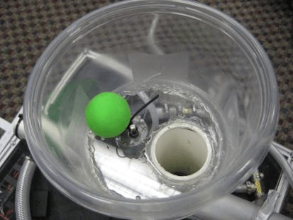
In order to be able to pour six balls into our device and have those balls load, one-by-one, into our barrel, we needed a loading hopper slightly more sophisticated than a passive funnel. First, the hopper had to have a large enough opening, such that the balls could be poured, instead of carefully placed, into the device. In addition, the balls, once poured into the device, had to align themselves such that we could feed one ball at a time into our barrel in preparation for firing. To achieve the above-stated goals, we designed the hopper system shown in Figure 11.
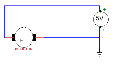
A 5” diameter plastic container, mounted to an acrylic plate, sits above the firing barrel, atop a vertical PVC pipe of 2” inner diameter. This large-diameter container allows the nerf balls to be dumped into our device, rather than placed one-by-one into the PVC pipe. The acrylic plate has a large hole, such that it fits around the PVC pipe. Thus, the acrylic pipe is rigidly attached outer-diameter of the PVC pipe and the top of the plate sits flush with the top of the PVC. A small DC motor with a zip-tie attached to the shaft is mounted to the acrylic plate such that the shaft sticks into the ball-housing area. The zip-tie acts to agitate the balls, moving them around in the container so that they all fall into the PVC pipe, and are thus ready to be loaded into the barrel.
The PVC pipe acts as a vertical column to organize the balls. The column is directly attached to the barrel. Once the balls fall into the column, and align themselves vertically, the loading into the barrel is purely a function of the retraction of the piston. That is to say, when the piston retracts, the hole in the barrel opens up, allowing for the ball lowest in the vertical column to gravity feed into the barrel. The piston then moves forward, preventing a second ball from loading into the barrel, while pushing the loaded ball forward to prepare for firing.
<
p align=”center”>
<
p align=”center”>
The results [iframe src=”https://player.vimeo.com/video/41849420″]