I recently purchased Lego’s new NXT hobbyist robotics kit. After familiarizing myself with the basic layout of the command module, available hardware and sensors, and third-party programing languages by building several single-task robots, I decided to use the NXT as a forum for my studies in SLAM robotics. As I have previously quoted, Dr. John Leonard of MIT says,
The problem of SLAM is stated as follows: starting from an initial position, a mobile robot travels through a sequence of positions and obtains a set of sensor measurements at each position. The goal is for the mobile robot to process the sensor data to produce an estimate of its position while concurrently building a map of the environment.
My goal and new perspective on the problem is to design a system which is as simple as possible. I immediately realize that much of the complication in SLAM systems lays in the timeliness with which the system processes information in real time. I know that some compromise between speed and simplicity had to be established, and in pursuing the most simple system, I am willing to sacrifice a lot in speed. So I have created what I am calling the “slam five robot”. The real acronym is S.S.S.S.S.L.A.M. which stands for “super-simple, super-slow, simultaneous localization and mapping robot”.
The system consists of three components: the physical hardware of the robot, the control algorithm which guides the hardware and sensors, and the post processing algorithm which interprets the sensor data. I begin here by describing the hardware and sensor setup.
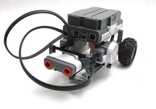
Front view of the SLAM-5 bot, showing ultrasonic range finder and wiring for the drive motors.
I established several design criterion through some quick concept generation, subsystem building, and two ground-up rebuilds. The robot needed to be as small (i.e. compact) as possible to fit into small spaces. The “seeing” needed to happen via its ultra-sonic range finder (USRF) (it being the best suited of all the already included sensors). Locomotion should occur by two independently driven wheels in the rear with one unpowered, omindirectional wheel in the front. The encoders in the two drive wheels allow for highly accurate measurements of both forward and turning movement. The USRF should be approximately 2 cm off the ground so as to see both obstacles that the robot can not climb and walls for mapping. All of this led me to build the robot which I’m calling “charlie”.
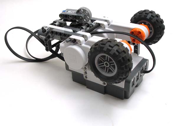
Upside-down view, showing passive steering wheel in the front and two, independent drive wheels in the rear.
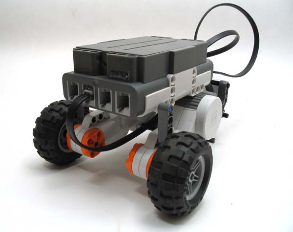
Rear view showing drive motors and wiring for the USRF.