3/7/2017 UPDATE: A commenter made some nice updates to both the translation and the geometry of the project. Be sure to read Martin’s comments below.
1/2/2014 UPDATE: After some interest from other folks in this project, I’m sharing all of my final Solidworks files. I’ve talked with the original sponsor and he has agreed to release them. You can download a zip file here. The files are organized by part. All of the final drawings and parts are annotated with “_finished” in the filename. Some of the original scans are also included.
3/31/2013 UPDATE: A kind reader has found the original drawings in a model airplane magazine from 1964. I’ve included the PDF below in the Resources section. The blue prints are on pages 17-18. It is interesting to note that the model was submitted as an entry to a contest to generate an epitrochoidal engine (an epicycloid is a type of epitrochoid). However, as I show below, the chamber isn’t an epicycloid.
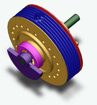
I have been contracted to convert the SW92 Wankel rotary engine from its original 1950’s paper format (in German) to electronic format (in English). I am utilizing Solidworks 2005 to reconstruct 13 of the 36 pieces included in the blueprints. Furthermore, I am relying on a tremendous effort from MacField Young to perform most of the German to English translations. The sole purposes of this blog entry are to communicate with my contractor, to document my progress, and relay certain concerns. In other words, this entry is a work in progress finished!.
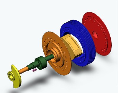
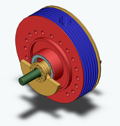
Table of Contents Part 1. Cylinder Part 2. Rotor Part 3. Front Casing Part 4. Rear Casing Part 5. Eccentric Shaft Part 6. Front Counterweight Part 7. Rear Counterweight Part 8. Pinion Gear Part 12. Screw Nut Part 13. Screw Nut Part 14. Bushing Part 18. Fitted Key Part 26. Locking Screw Assembly Views Epicycloid Concerns Gear Concerns Accompanying Text Translation Resources
Part 1. Cylinder, Zylinder Ω Translations and Explanations: – Ansicht A: view A – Schnitt A-A: Cross-sectional view along the plane marked with the two A’s (in the right drawing) – 1/4″ 32: 0.25 inch threaded hole with 32 threads per inch (UNEF standard) – 11H7: 11mm hole with tolerances +0μm/+18μm (ISO standard) – geschliffen 10my: honed to a roughness of 10 μm – verchromt: chrome plated – katen scharf: edges sharp (no beveling) – verbahren mit Teil 27 u 33: drill holes assembled with parts 27 and 33 to ensure exact fit – 16 x M4: 16 uniform threaded holes with 4mm major diameter and “normal” coarse 0.7mm pitch (ISO standard)
Problems:
– “00,2” vs “0,02”
– What are the chamfer dimensions on the fuel injection port? What is the depth of the rectangular hole?
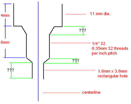 Answer: For now, treat chamfers as 45° and assume that the hole is deep enough to fully enter the combustion chamber.
Finished Product:
2. Kolben (rotor) Ω Translations and Explanations: – Bohrung 29 …. einsatzgehärtet bis zu einer Tiefe von 0.8-1 HRC58: The bore hole … has to be case-hardened to reach a hardness of HRC58 with the case hardening reaching a depth of 0.8 to 1mm. – geschliffen 10my: honed to a roughness of 10μm
| Verzahnung P=0 gear teeth | |
| Korrigierte Zähne corrected teeth | |
| Zänhezahl number of teeth | Z = 21 |
| Modul module | m = 1 |
| Halfwinkel nominal pressure angle | α = 20° |
| Zahnhöhekoeffizent addendum coefficient | y = 1 |
| Zahnverschiebung tooth displacement | x·m = 0,43 |
| Maß de Rolle dimension or proportion of the caster/roller | 19,62 + 0,06 |
| Rollen durchmesser caster/roller diameter | 1,65 -0,01 |
Finished Product:
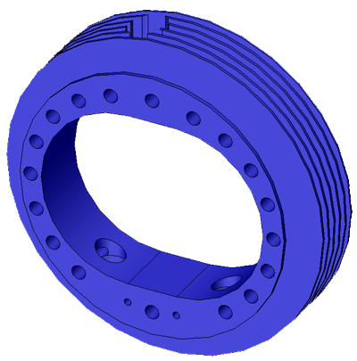
3. Front Casing, Vorderwand Ω Translations and Explanations: – M29 x 1: threaded hole with 29mm major diameter and 1mm pitch – 4H7: 4mm hole with tolerances +0μm/+12μm – 28H6: 28mm hole with tolerances +0μm/+13μm – mit Teil 1 u. 4 bohren und reiben : drill and grind (to exact tolerance) holes assembled with parts 1 and 4 to ensure exact fit – geschliffen 10my: honed to a roughness of 10μm
Problems: – It is my opinion that the M29 x 1 threaded hole is a very fine thread pitch. Confirm that the machine shop has the capabilities to tap such a large hole with such a (relatively) fine thread.
Finished Product:
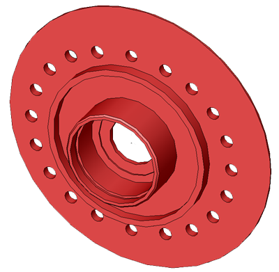
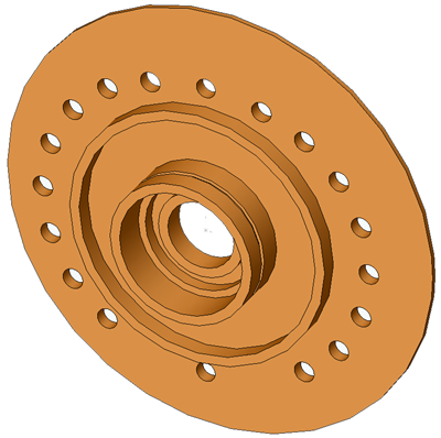
4. Rear Casing, Hinterwand Ω Translations and Explanations: – M30 x 1: threaded shaft with 30mm major diameter and 1mm pitch – 14H7: 14mm hole with tolerances +0μm/+18μm – geschliffen 10my: honed to a roughness of 10μm – mit Teil 1 u. 3 bohren und reiben : drill and grind (to exact tolerance) holes assembled with parts 1 and 3 to ensure exact fit
Problems:
I believe there is an error in this drawing. The arrow should be extended as seen below:
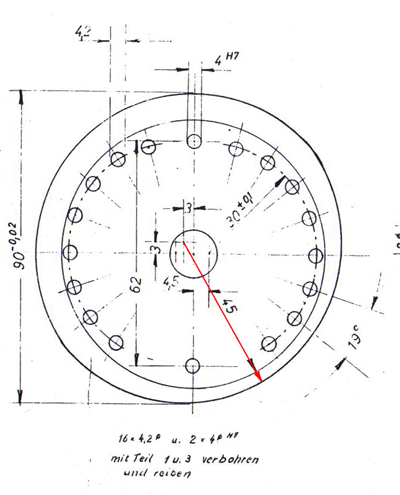
Finished Product:
5. Eccentric Shaft, Exzenterwelle Ω Translations and Explanations: – 4H7: 4mm hole with tolerances -12μm/+0μm – 9j6: 9mm shaft with tolerances -0.045μm/+0.045μm – 24h6: 24mm shaft with tolerances -0.13μm/+0μm – 12j6: 12mm shaft with tolerances -0.055μm/+0.055 – 10n6: 10mm shaft with tolerances +0.12μm/+0.23 – M8: threaded shaft with 8mm major diameter and 1.25mm pitch – Flache 24h6 einsatzgehartet bis zu einer Tiete Von 0,8-1 HRC 58: Surface 24h6 case-hardened to a depth of 0.8-1.0 and a hardness of HRC 58 – zul. außerzentrische Lage des B u. C in Bezug auf A = 0,02: Allowable outer centrical layer of the diameters B and C in reference to A = 0.02 – Ubergangsraclien r = 0,5: transfer (transition) radius = 0.2
Problems: – “00,2” vs “0,02” – The notes make reference to a dimension “A” however, no dimension is shown in the drawing.
Finished Product:
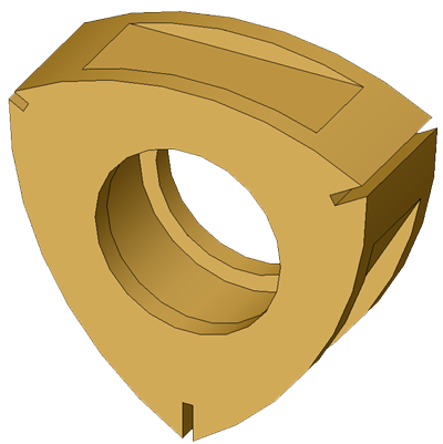
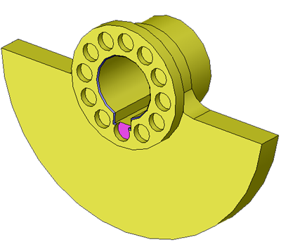
6. Front counterweight, Gegengewicht vorn Ω Translations and Explanations: – 10H7: – nach Weigen heir Material wegnehmen: after weighing remove material here (for balancing)
Problems:
– A discrepancy exists in the drawing between what is shown and the dimensions provided. The right most drawing shows no overlap between the rectangular notch, which runs the axial length of the part, and the circular array of holes. However, based on the given dimensions, the bottom hole (highlighted in purple) overlaps the notch by 0.5mm as shown below.
 – The drawing shows two chamfered edges (shown below, both highlighted in blue) however, dimensions are only provided for one side. I have assumed that both sides are equally chamfered.

Finished Product:
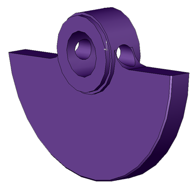
7. Rear counterweight, Gegergewicht hin. Ω Problems: – It is not evident in the original assembly drawing which direction the counterbalance slides onto the shaft. This should be determined during actual assembly. It should fit both ways and have minimal effect on the centrifugal balance of the system.
Finished Product:
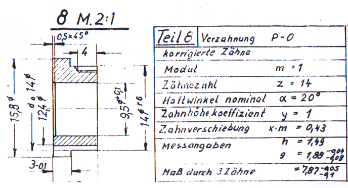
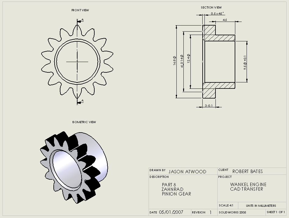
8. Pinion Gear, Zahnrad Ω Translations and Explanations
| Verzahnung P=0 gear teeth | |
| Korrigierte Zähne corrected teeth | |
| Zänhezahl number of teeth | Z = 21 |
| Modul module | m = 1 |
| Halfwinkel nominal pressure angle | α = 20° |
| Zahnhöhekoeffizent addendum coefficient | y = 1 |
| Zahnverschiebung tooth displacement | x·m = 0,43 |
| Messangaben measurement specifications/data | h = 1,49 g = 1,88 -0,04 -0,08 |
| Maß durch 3 Zähne dimension or proportion of three teeth | = 7,87 -0,05 -0,1 |
12. Screw Nut, Mutter Ω Translations and Explanations: – M29 x 1: threaded shaft with 29mm major diameter and 1mm pitch
Finished Product:
13. Screw Nut, Mutter Ω
Problems:
–
I assume that, like part 12, there are supposed to be two grooves which allow the use of a flat-head screwdriver to attach the part to the final assembly. However, only one groove is shown (i.e. the groove does not run along the entire diameter of the part. Furthermore, the one groove that is shown is located on the wrong face of the part, making the use of a screwdriver impossible. Currently the part is drawn as shown in the original document. A change can be made if needed. It is likely that this screw nut is tightened similar to a bicycle lockring, with a standard lockring tool.
Finished Product:
14. Bushing, Abstandsbuchse Ω
Finished Product:
18. Fitted Key, Paßfeder Ω Translations and Explanations: – M 2:1 – Drawn to scale 2:1
Finished Product:
26. Locking Screw, Sicherungs schraugbe Ω Translations and Explanations: – M 2:1: Drawn to scale 2:1 – M2: threaded shaft with 2mm major diameter and “normal” coarse 0.4mm pitch
Finished Product:
Epicycloid Concerns
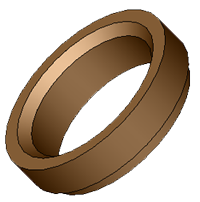
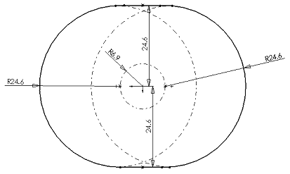
After reexamining the original blueprints it is evident that the combustion chamber (rotor housing) is not the standard k=2 epicycloid shape. The chamber is instead two semicircles connected by two parallel lines. The figure below shows a profile of the current semicircle combustion chamber.
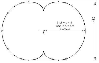
Next, a two lobed epicycloid, with dimensions which produce the same eccentricity ratio, e, and rotor radius, R, is shown. It is then “capped” on the top and bottom by two parallel lines. This shape does not produce the same vertical dimension of the chamber profile, thus proving that the shape in the original drawing is not an epicycloid.
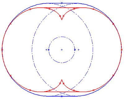
This distinction is even more evident when overlapping the two combustion chamber profiles.
The effects of such a change are not immediately evident. However, the power calculations below are based on the epicycloid shape and will thus need to be modified to fit the semicircle shape. It will be quite easy to produce additional drawings for the epicycloid chamber if so desired.
Gear Concerns There is a discrepency between the drawings and the accompanying tables for the external and internal gears (parts 2 and 8, respectively). Based on the parameters provided in the tables, I have used MITCalc to generate the total gear parameters as well as .DFX files which are then fed into Solidworks. The datum in the tables below shows the overall dimensions of the gears. The discrepency lies in the root diameter and tip diameter.
| Spur gear – Pinion | ||
| Module m 1 | ||
| Number of teeth Pinion / Gear | z1 | 14 |
| Normal pressure angle | alfa | 20 |
| Helix angle | beta | 0 |
| Reference diameter | d1 | 14 |
| Tip diameter | da1 | 16.672 |
| Face width pinion | b1 | 84 |
| Addendum modification coefficient | x1 | 0.43 |
| Spur gear – Gear | ||
| z1 m 1 | ||
| Number of teeth Pinion / Gear | z2 | 21 |
| Normal pressure angle | alfa | 20 |
| Helix angle | beta | 0 |
| Reference diameter | d2 | 21 |
| Tip diameter | da2 | 19.86 |
| Face width gear | b2 | 82 |
| Addendum modification coefficient | x2 | -0.43 |
In the drawing of the rotor, the tip diameter is 20.1mm and the root diameter is 24.4mm resulting in a 4.3mm tooth height. This tooth height is quite large for a 21T gear. This problem was observed by other hobbyists trying to build the SW92, specifically here.
Pinion Mounting – I do not understand how part 8 (the pinion), part 4 (rear casing), and part 26 (locking screw) interact. According to the parts list, four seperate locking screws are used. I do not see how these screws screw into the “edge” of part 8. Shown below are the original scan and my current rendering of the part. The “d_0 14” dimension corresponds to the 14mm diametral pitch of the gear teeth.
It seems as if other people have had the same problem: here. Some important details gathered from that forum discussion:
“The four M2x5 screws (part #26) are set into a non symmetrical hole pattern to ensure the stationary gear can only be fitted one way, as that is how the rotor is ‘timed’.”
Furthermore, the internal pinion gear (part #8) fits over the end of the eccentric shaft (part #5). However, the pinion has an internal diameter of 9.5mm. The shaft has a diameter of 9.0mm with a tolerance of j6 (-0.045μm/+0.045μm). This 0.5mm difference suggests the presence of some quite tight needle bearing, however none is shown in the overall diagram.
Accompanying Text Translation (This translation was completed by Mark Wrathall and copied verbatum from here. It is neither the work of myself or MacField Young.)
The SW92 was designed in 1960 – 1962 by Dipl Ing Julian Faleki of Poland, and has the following specs: Swept volume…………………………………9.2 CC Compression …………………………………….7.4:1 Max Power output……………..……………1.5 HP Power at 12000rpm…………….………….……1HP Fuel……………………………………Methylalchohol Lubricant……………………….10-20% Caster oil Glow Plugs…………………………………Start 1.5V Weight……………………………………….900-930g Eccentricity…………………………………….3.5mm Major Radius…………………………………….28mm Rotor thickness………………………….…….18mm Apex seal replacement interval……….….30 H Building Instructions. [ 1 ] Rotor Housing. Study the plans carefully for the location of the housing screw holes. The sharp edges of the rotor housing are manufactured by first machining the housing 1-2mm wider than plan then, after chroming, they are ground to dimension. The inlet and exhaust are radiused to exactly 0.5mm. It is important that the M4 holes are carefully drilled with equal spacing, especially in the area of cut B-B. The countersink diameter should not exceed 5mm. Accuracy is extremely important, otherwise sealing and compression will suffer. [ 2 ] Rotor The seal slots must be symmetrical to ensure good sealing. The given angles must be maintained, and the axis of symmetry must cross the centre line. Through lapping of the sides of the rotor, using lapping paste on a surface plate, you are aiming for the following tolerance: The middle of the rotor should be 4 to 5 microns wider that the corners. [ 3 /4 ] Front and Rear Housing Here it is important to follow the correct order of set ups. First you turn a ring of OD ~110mm ID 90 (–0.02mm) about 30mm wide. This ring is the assembly jig. Press the phasing gear [8] in the rear housing, and then insert the bearing. Install the needles [16], the rotor [2] with tensioners [11], springs [10] and apex seals [10] ontothe E-shaft [5]. The rotating assy is inserted into the rotor housing, and the end housings fitted. Slip the assembly jig ring over the housings, then rotate the rear housing until the E shaft turns freely in both directions without any binding. Now the 4mm holes are bored in the end housings with the jig ring in place. After disassembly, the holes are enlarged to 4.2mm and the R45 finished. Some Assembly Hints. Before assembly, the entire rotating assembly should be statically balanced. This is performed on pair of knife edges. The rotor and needles are installed on the E-shaft with plenty of grease. The forward counterweight [6] with it’s key [18] and rear counterweight [7] with it’s pins [20]. The Phasing gear [8] is secured with 4 screws. It has teeth. The mounting holes are not symmetrical. These bolts should be safetied by peening . The bearing [35] is fitted to the rear housing, with sealing rings [15] on each side, and secured with the nut [13]. The front main bearing [36] with it’s seals [19] is fitted to the forward housing, secured by a nut [12], which must be safetied with a split pin. Both bearings should be lubricated with caster oil. The exhaust [33] and intake [27] are secured with set screws [34]. The spray bar needle [30] is soldered into the knurled thumbscrew [29], such that the 0.9mm hole in the spray bar can be completely closed. The main housing screws [24] and mount screw [25] are torqued evenly in a cross pattern. If your work is of sufficient quality, no gaskets or sealant will be necessary. Starting. First check that the engine turns over without binding. The compression is checked once the glow plug is installed. The resistance to rotation should be less than equivalent piston engine. For the first runs, choose a prop of around 250m diameter. The fuel tank must be above the level of the spray bar. During running in, a fuel of three parts methylalchohol to one part caster oil by volume is appropriate. You will need a conventional starter giving 3000 – 4000 rpm, although a bend grinder can also be modified for this purpose. Troubleshooting. If the motor requires greater starter speed to start than mentioned above, then the rotor to side housing clearance is too loose. On the other hand, if the rotor to side housing clearance is too tight, it can miss, or nip up in service. These symptoms can also occur due to excessively lean mixture, or a propeller of insufficient mass. With insufficient cooling, the motor will tend to miss. If the rotor to side housing clearance is correct, then the motor will run in relatively quickly. It is considered run in when it runs without hesitation to 12000 rpm. The fuel-oil mixture can then be altered to 10-15% caster oil, whereby the higher the percentage of oil, the easier the engine is to start, at lower starter RPM.
Resources: – ISO 286-2 Hole and Shaft Tolerance Table (.pdf) – German/English Gear Symbols – Wikipedia: Corrected Teeth – Epicycloid Macro for Solidworks (written by kellnerp) – Forum Discussion on Machining the SW92 Engine – Aero Modeller 1964 – original engine blueprints
Good afternoon.
I am building a prototype of a Diesel cycle Wankel engine, and found your Wankel CAD work updates on tir38 while looking for information on rotor geometry. I have found the geometry of the rotor housing discussed at great length, but very little on that of the rotor – it is usually approximated as a slightly bulging equilateral triangle. I understand that maximum compression ratio is achieved when the rotor is some kind of epicycloid. In making your models, did you learn anything about the nature of this shape?
If you are interested, I will of course keep you posted on the project, and give you any credit due for geometrical information regardless.
Thank you for your help.
The original German drawing of the rotor can be found here:
https://jasonatwood.io/wankel/scans/
It is part of the public domain.
To clarify, the housing is the epicycloid shape. The rotor is as you describes: an equilateral triangle with “rounded” sides. Each side has
a constant arc. i.e. it is part of a constant radius curve. The critical aspect is the center and radius of this curve.
Keep me up to date on your progress because I’m interested to see this work continued.
Hi,
I am a mechanical engineer myself, I’m impressed.
I am thinking of building a small cheap motor for myself to play with and check some theories I have. your motor looks pretty much what I am looking for.
I have a mill I can make my own parts here. can you give me some help pulling this thru?
thanks,
Shlomi
Sure, What type of help are you looking for, specifically?
GOOD WORK,BUT WHAT ABOUT THE OTHER 23 PARTS?
ARE THEY OFF-THE-SHELF PURCHASED PARTS. I WOULD LIKE TO TRY AND SCRATCH-BUILD ONE. IT USES TOO
MUCH FUEL AND IT WEARS TOO FAST. WHAT CAN BE USED
FROM 13B AND rx8-2007 MODEL YEAR? I NEED A 2007
FACTORY MANUAL. DO YOU KNOW WHERE? IT NEEDS
REIMAGINING. vERY GOOD WORK PROJECT. dj
No. They are all custom parts. The original drawing is now public domain, if you can find it. I am thinking of purchasing a copy, scanning it, and uploading it here. Check back at some point.
Hi,
This site is a great help.
I am trying to 3D model the SW92 Wankel. Unfortunately there are still some dimensions missing, no assembly drawing etc.
I’m looking for someone who would help me out in getting the missing information and perhaps giving me a few tips…
My plan is to model the SW92 first, then scale it up to a larger size and fabricate a prototype for a large scale model plane (about 100cc). I don’t need to use the SW92 as my pattern, by this is the only Wankel I found with almost complete set of drawings.
Thank you,
Andrew
Thanks! If you can let me know what dimensions are missing I can check my models. As I say in my initial post, I only needed to model some (not all) of the parts. The original scans are here: https://jasonatwood.io/wankel/scans/. I have since tried to find the original blueprint online but I’ve been unsuccessful.
If you are attempting to fabricate a Wankel engine, I’d suggest http://www.cnczone.com. There is regular discussion amongst machinists taking on the same challenges you suggest.
Hi, a complete assembly drawing is in this aeromodelling magazine (page 16), even though some parts are still missing and all notes are in Polish
As optional project for my Drawing class final, I’ve managed to complete the SW92 Wankel engine with some minor adjustatment and by guessing some mating. I could send you my SolidWork project if you’re interested, but please note that I haven’t had any Machine class yet.
Excellent find! I’ll save the .pdf and link to it in my post above. If you have a site with your project on it, feel free to post a link in the comments.
Is there any way possible that you would supply your CAD drawings? In Iges or Step, Please!!???
I don’t even care if it runs or not. I would like to machine it out of Acrylic and stain it differing colors. That way it could be put on display and rotated.
Thank you for your time and trouble!
LennyWayne
Hi,
the epitrochoid in the original blueprint is not so bad..
The epitrochoid with the parameters R= 27.5 mm; e= 3.5 mm; a=0.5 mm
give a difference of maximal 0.1 mm
I’ve made a Excel-sheet to check the parameters:
In C2: 3.5 (e); in C3: 27.5 (R)
A5 – A605: 0 – 600
B5: =PI()/100*A5
B6: =PI()/100*A6
and so on to B605
C5: =$C$2*COS(B5)+$C$3*COS(B5/3)
C6: =$C$2*COS(B6)+$C$3*COS(B6/3)
and so on to C605
D5: =$C$2*SIN(B5)+$C$3*SIN(B5/3)
D6: =$C$2*SIN(B6)+$C$3*SIN(B6/3)
and so on to D605
marked C5 to D605 -> Point (XY) Diagramm gives the shape of the epitrochoid
[a] is the parallel distance to the epitrochoid (because of the apex seal radius)
The travel of the apex seals in the easy to machining shape is 0.16mm
(0.1 outside, 0.06 inside)
Hello,
I would like build this engine with your drawing. Please could you tell me the material for all parts .
Regards
JPierre
I believe all of the materials are marked in the drawings.
Congratulation ! great work, i love wankel engines.
all time the best
Reinhard
Epicycloid concerns, yes you should have used an Epitrochoid:
http://scot.tk/re/Trochoids/Trochoids.htm (BEST info)
https://en.wikipedia.org/wiki/Epitrochoid
NOT
https://en.wikipedia.org/wiki/Epicycloid
Make a custom rotary using:
Download and install the application
Than you can see the different usable geometries
It would be an eye-opener
Do you care to add any more detailed comments?
hai, i am vinod doing my thesis on wankel engine. I want calculation and blue print to design wankel engine in solidworks. Please help me to find the calculation for rotar.
Can you be more specific? What calculations are you trying to perform?
Hi Jason,
thanks a lot for sharing all this information! I purchased the plans from vth.de a while ago and am dreaming of my own SW92 some time in the future, when my skills will be sufficient. 🙂
I see that the original posting is about 10 years old, but at least there are your updates from 2014 and I hope the following might be helpful for somebody who stumbles over it in these days.
So one annotation to your translation: “reiben” in this context does not mean “grind”. It is an operation performed by a tool called “Reibahle” which is called “reamer” in English. So “ein Loch (auf)reiben” means to ream a hole.
And a thought about the 0.5 mm difference between parts 5 and 8:
The stationary gear #8 is a press fit (H7 / r6) into the rear casing #4 on its 14mm diameter, so firmly centered by that. As the excentric shaft #5 is positioned by the two ball bearings in the front and rear casings, those 0.5mm are quite certainly just a relief to keep #5 and #8 from interfering with each other. No need to put an additional bearing at this place.
Regards
Martin
Martin,
Thanks for the great input. I’ll make an update in the original text.
Hi Jason, fascinating article, thank you. The download link for the SolidWorks zip file is no longer valid. Are you still able/willing to share these?
Dale,
Thanks for letting me know. I’ve updated the link and I can confirm it’s working.
Hi Jason, I was just revisiting my unfinished downloads and saw your reply. I am very grateful. I recently retired from corporate life to focus on interests like this and restoring old motorcycles, etc. I am sure you understand. Thanks again. Regards, Dale
Hello, Jason. I got a thesis about a wankel engine with 3.5 kW power. Could you please send me the calculations of the engine you installed on the site? I’d love it if you put it in a drive or somewhere else.
could I 3d print this than cast it??
FWIW, I have released the SW-92 SolidWorks files created by Jason on GitHub for anyone interested in tinkering with it. Due to copyrights, I unfortunately can’t release the original plats.
https://github.com/arpieb/Wankel-SW92
Enjoy!
Robert,
Glad to see you still have these.
Perhaps. I don’t know how strong it would be. I think you’d also want to ensure the rotor is perfectly balanced. My guess is that a cast rotor would not be very uniform.
Hopefully better late than never, have uploaded the scanned original plat to the GitHub repo:
https://github.com/arpieb/Wankel-SW92
I’m curious, are you aware of anyone machining and building the engine from your models? If so, can you point me anyone documenting or discussing their project?
Thanks!
Sorry no I don’t.